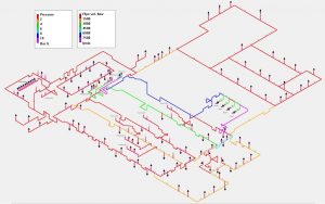

PIPENET Standard Module has anumber of applications such as air, water, steam utility systemsdesign, and ventilation (HVAC) systems design.ĭownload Links : Sunrise PIPENET VISION v1.
PIPENET AND PIPEFLO SOFTWARE
PIPENET Transient Module is widely usedfor water hammer and steam hammer, hydrocarbons, and surge analysisof fire water systems.Ī steady state fluid flow analysis software for compressible aswell as incompressible flow. This module can be used for a wide range of design orsprinkler systems, ringmain systems, and foam solution systems.Ī versatile, user friendly and extremely powerful software tool formodelling unsteady state phenomena, and calculating the resultanthydraulic transient forces. Specifically intended for the design of fire protection systems.PIPENET Spray/Sprinkler complies with the NFPA13, NFPA15 and NFPA16rules. Each is independent, so PIPENET modules can be licensedseparately or in any combination. PIPENET Leading the Way in Fluid Flow Analysis Application Bulletin Process Industry PIPENET Transient Module Case Study Cavitation Elimination in Long Vertical Pipeline BACKGROUND The project under investigation is a light crude oil transportation system, located in China. Brazil, Colombia, Ecuador, Mexico, and Peru, and this list also comprises 5 of. The result is the three world leading modules ofPIPENET. These K-values may be used to determine the pressure loss from a fluid flowing through these entrances and exits. Colombia representa el 1,3 de la produccin mundial y ocupa el puesto 13 en el ranking mundial entre 91 pases productores.

This article provides K-values for pipe entrances and exits of various geometries. Three software modules ensure that, nomatter how extensive or complex your network, PIPENET will perform.Each of the three PIPENET Vision modules has been expertlydeveloped for a different range of applications, taking input fromour customers. When a fluid moves from a tank or vessel into a pipe system or vice versa there are pressure losses. PIPENET is the leader for rapid flow analysisof pipe and duct networks. The K value may be converted into head loss through multiplication with the fluid velocity head as shown in the equation below.Software Description: Sunrise PIPENET VISION v1. Section 3 presented the equations required to determine the pressure loss through various geometries in terms of K values. Generally the more abrupt the change the higher the losses, while more gradual changes result in much lower pressure drops. The degree of permanent pressure lost through a pipe size change is dependent on the geometry of the size change. In a perfect system if the fluid then entered a larger pipe and decelerated the kinetic energy of the fluid would be converted back into pressure. Pressure changes due to acceleration are reversible, for example in a system where the pipe area decreases, some potential energy in the form of pressure is converted to kinetic energy as the fluid is accelerated in the smaller pipe, reducing the fluid pressure in this pipe. As the name suggests the permanent pressure loss is not recoverable, and like the pressure loss through ordinary fittings such as a pipe elbow, it is lost to friction, eddies, and noise.

There are two components to the pressure loss/gain through an area change, the permanent pressure loss and the change due to acceleration. FluidFlow will propose the most economical pipe size based on physical property data. Accelerate the design process and avoid unnecessary over-sizing of piping and equipment, saving both design time and capital cost. Changes in flow path area where a fluid may be accelerated and/or decelerated such as restriction orifices, pipe reducers and expanders, venturi meters etc. FluidFlow offers a fast and effective approach to automatically sizing piping and associated equipment.


 0 kommentar(er)
